If you’ve been following this series of questions, you are probably genuinely wondering why the hell we have taken an apparently massive departure from CIE chromaticity diagrams that map visible light to a stupid model, over to fundamental and equally dumb light intensity and geometry with Question #20. We have one more question before we can glue the two halves together.
This is essentially inspired by Jim Blinn’s A Trip Down the Graphics Pipeline. We are going to take a trip down the pixel input to output chain, from slider to light output. It won’t answer all of the questions you will have, but it will at least get you asking the right things about what your stupid software might be doing.
WARNING: There’s a small bit of math involved, with the answers provided. Feel free to punch the math into a calculator if you so desire, or just punch a wall if it is already stressing you out.
The point isn’t to confuse you with math, because frankly, math is boring as f*ck and stinks. With that said, it is critical to understand the conversion between an encoded and decoded value sent to a display and what happens. There’s no other way to really understand the mechanism than to swallow a tiny bit of bitter math. What’s more troubling for this question is that there are plenty of horrible illustrations. The illustrations are far worse than the math.
So let’s hunker down and do a little pixel f*cking…
Question #21: How do we display a red pixel at a certain intensity on a display?
Being airy fairy butterfly “creatives”, everyone does plenty of imagining. We are going to carry that trend forward and imagine a display with exactly two pixels. For our purposes, we will assume that it’s a commodity sRGB-like display. Tada…
Now imagine if we turned on each pixel to full intensity. If we were to take a peek at the three little lights within each pixel, we’d see something possibly like…
While it’s extremely useful to remind ourselves that there are indeed three lights that comprise an individual pixel, the more common way we see pixels is as though we are far away from that tiny geometry, and we perceive the three lights as a cumulative sample of their projected wavelengths. In this case, the result is sRGB’s D65 white point chromaticity, which looks like this if you are on something actually displaying sRGB’s D65 chromaticity correctly…
Whoops! We skipped the part where we are dialing our DCC’s application slider to control the lights. Why is this important? Because until we peek into what is happening between a typical RGB slider and the output from a display, we won’t be able to solve the Riddle of Question #9.
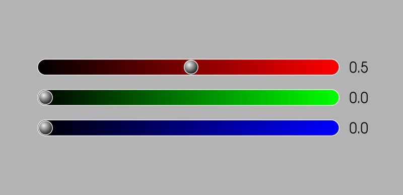
So let’s make this a little more clear. Let’s slide only the red slider on the upper pixel to 100% code value, and we will leave the lower pixel set to code value 0%…

The slider means 100% emission right? Hold your horses! Remember that we are always dealing with relative values and that we have to connect the values to meaning. This is an absolutely crucial thing to work through in our minds. Granted, it’s tiresome as hell, but hang in there…
In the above example, we are imagining that our application has the sliders connected directly to our sRGB-like commodity display. That display, as we learned back in Question #6, has a hardware decoder built into it! Before it converts the code value into an electronic signal and emits the radiometric-like linear quantities of light, it always decodes the encoded value it receives. It’s not smart and is closer to a sausage machine; it does not care what meat you put into it, it treats all meat the same.
In this case, our sliders communicate to us, the creators, in those code value labels. That is, the value of 1.0, or 100%, is does not quite mean 100% display emission light! It’s a code value. The code value will get decoded by our display’s hardware in some kooky math manner. Let’s step into that process…
In this case, our sRGB-like commodity display takes all values it receives and decodes them via its specific transfer function, just like the sausage machine. That is, if we send a code value of 1.0 to this particular display, it will take that value and decode it to via a math formula of some sort. For commodity sRGB displays, that formula is:
encoded_value2.2
So how to decode our slider’s code value of 1.0? Just plug it into that formula.
1.02.2 = 1.0
Well that was a bit of a let down right? Our input code value of 1.0 comes out as a display linear light ratio of 1.0. That means that our code value of 100% of the code value range happens to end up 100% display linear light output.
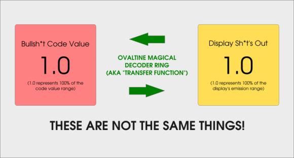
But wait, isn’t that the same f*cking thing?
No. No it’s not.
It is very important to realize that even though the values end up identical, they mean radically different things. Even code value 0.0 does not mean 0% display linear light output, but rather it too must be decoded first!

1.0 are the same, but the meaning is completely different. Don’t let identical numerical values seduce you into thinking they hold the same meaning!With the hope that we will never conflate two identical values with identical meaning again, let’s look at the result…
What a huge amount of waffle to hammer a point home when the result is pretty damn expected, right?
So let’s do a slightly more tricky value. Let’s say that we want the sRGB-like display to pump out 50% of the overall light level from the display. What does that look like? First we adjust our slider to 50%, right? Right? Right?
Wrong!
Remember that the slider represents the encoded value range of our display’s transfer function. That means that the values do not represent display linear light ratios of emission, and the values do not even attempt to represent an idealized perceptually uniform distribution as per Question #15. They are simply encoded values. That encoded value in turn will get decoded by the display, and turned into display linear light ratios.
How then, do we figure out to control the display’s linear light ratios directly? We have to flip the display’s output transfer function around!
We want a display emission that is 50% of our maximum emission of the display light range. How do we get that? We need to flip the transfer function of the display backwards. So if our display’s transfer function for output is:
encoded_value2.2 = display_linear_light_output
We need to invert that transfer function to get it flipped around the other way. “Invert” here, by way of boring math, means we will divide 1.0 by the exponent:
display_linear_light_output(1.0/2.2) = encoded_value
That probably looks a little scary, but don’t let it freak you out.
The important part to understand is that we have two sides to this problem. One side is the encoded value, the other side is the decoded value. This happens in the hardware of the display itself, and all displays have some sort of hardware decoding thingy. In our case, the encoding is not too complex and is a simple power function of a simple value. Again, for those whose eyeballs rolled back into a glazed donut drooling automaton state the first time…
So let’s plug our desired linear light ratio into our function above and see what encoded value we get back…
0.5(1.0/2.2) = 0.73
Don’t let the math scare you. On the left side we put our desired 50% value, or 0.5 in geeky math, into that flipped around backwards version of the display’s decoding function exponent formula thingy.
The result is the magic encoded value of 0.73 we need to send to the display1. The display in turn will do exactly the thing it did in our first example, and push it through it’s hardware decoder sausage maker:
0.732.2 = 0.5
If you want, give it a shot using a calculator. Even if you don’t, hopefully you can get a sense of the encoding to decoding that is always happening with hardware displays. Your iPad Pro? Yep. Your sRGB display? Yep. Your Adobe RGB display? Yep. Your HDR television? Yep. There’s always a unique transfer function buried in that hardware that is responsible for decoding the magically encoded code value it is handed! Let’s set our slider…
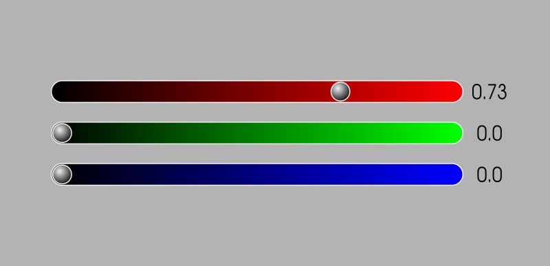
So, as per our example, what does that 50% total display emission output, aka sRGB-like code value 0.73, look like for only the red pure sRGB primary light? Here it is…
0.73, decodes to exactly 50% of the overall emission strength for the red light in our two pixel display. Phew.Well that was a f*ck of a lot of work to get our minds around display linear light output, wasn’t it? You might be skeptical that this will have a visual impact on your creative work, and rightfully so.
Would you believe it if someone told you that, despite the rather simple connection between display encodings and their respective meanings in linear light quantities, that a vast majority of software absolutely sh*ts the bed here? The software sh*ts the bed so hard that we see nasty-ass looking fringes that we were introduced to in Question #9, gaudy looking transitions in motion picture dissolving, gnarly fringing when we paint, completely incorrect light colour mixing, and wildly crazy incorrect interpretations of code values that leave the output completely broken. Some woefully informed folks at companies are even treating mishandling of colour as a marketing upside.
So why did we take this pedantic trip from sliders to display output? The important thing to remember here is that there isn’t some magical universal standard for what some random application developer decides to make their sliders do. There’s also no magical operating system that will insulate you from application developers from completely screwing things up. Typically, the developers don’t really have a clue, and those that do have a clue are probably helpless and as frustrated as we are. That means that we, as airy fairy creative butterflies, need to constantly keep our wits about us and prevent the hostile software from bungling our work.
For our purposes, digital colour is related to slippery concepts, and the only way to make them not-so-slippery is through a series of overly simplistic examples. In most cases, RGB sliders are directly related to the code value range of some transfer function, or worse, some random computer formula.
With that said, rightly or completely and absolutely wrongly, it’s extremely common that the slider values are the sRGB transfer function, which differs slightly from the commodity example exponent formula we used here2. Practically, in real-world scenarios, there are many complex things that might happen, including stuff that happens under the umbrella of colour management. In the end though, whatever the path is, the value will always be converted to an RGB code value for the display3, which in turn will decode it to display linear light ratios. Always.
So let’s answer our question and get the hell out of this math bog…
Answer #21: In order to get display linear light out of a display, the display linear light ratio is encoded to a code value range according to the unique transfer function of the display hardware encoding.
The code values are frequently not ideally perceptually uniform, meaning 0.5 in your slider isn’t some sort of useful metric in most cases, but rather often a ballpark approximation. In addition to the problematic reality of no such idealized perceptually uniform model existing, the reason the encoded values are not perceptually uniform is because they are a compression scheme based on the design of the display characteristics with respect to its intended usage. They typically are sort-of-kind-of close to being sort-of-kind-of-perceptually-uniform-ish-y, but it is a nuance worth distinguishing.
So why did this whole damn question have two pixels instead of just one? That’s a great question that will carry over to the magical gluing of many concepts together. Go grab a quarantine coffee before moving along to the next question…
1 Nope, there won’t be any WANKer conversion to eight bit code values here. Remember? They stink and make things way less comprehensible than they already are. If you are hell bent on doing so, feel free to multiply the code value given by 28 - 1. But honestly… do yourself a favour and think in terms of ratios and good, old fashioned, sane decimal representations.
2 Many folks and software screw this up all over. The canonized transfer function in the sRGB specification defines a two part encoding formula that is close to being the pure 2.2 power function described here. It is important to note that not only is 2.2 the not the canonized sRGB output transfer function (EOTF) in some discussion circles, but also that many displays aren’t technically sRGB because of this. In short, as a digital pixel pusher, it’s important to realize that your work will appear subtly different in the shadows if something screws this detail up. For more information, the official sRGB specification can be purchased here. The clarification as to the intention of the sRGB EOTF is provided via the excellent Colour-Science website link here. The specification could certainly use some clarity to carry us forward into the future, as the specification’s intention is subject to debate and discourse.
3 A million WANKers just screamed out that some displays use HDMI cables and that in turn, it isn’t RGB signals going down the pipe. The bad news for the WANKers is that displays will almost always have those little RGB lights in them, and that means no matter what is shoved down the cable, be it YCbCr or otherwise, it begins and ends its life as RGB ratios. Keep screaming, no one can hear you…

3 replies on “Question #21: How the F*ck do we Put a Red Pixel on the Screen?”
I’m wondering if you can go into more detail about this bit here: “With that said, rightly or completely and absolutely wrongly, it’s extremely common that the slider values are the sRGB transfer function…”
I thought I was understanding things but this part seems confusing to me. Let’s start with the base case for context: I’m using a sRGB display and I happen to pick a color red that is 73% of the way to my slider’s maximum; I understand that the value that’s really stored internally happens to be 0.5 because of the sRGB transfer function.
Assuming that’s correct, I have 3 more questions now.
1) If I’m sitting in front of a P3 display, the “same” color (for various definitions of same) let’s say sits at 70% of my slider’s maximum. Are you saying that it would actually still appear to sit at 73% of the maximum because slider values are typically sRGB in most software?
2) Regardless of the above, pretend that 70% is the correct value for P3 encoded values. Would the P3 transfer function still result in 0.5 being stored internally? I think yes.
3) It seems to me, and to further reference Q10, some transfer functions (compression schemes) are less-lossy than others. i.e. P3 is making better use of the 0 to 1 space after decoding than sRGB. Is that a fair statement? If so, minimizing the number of conversions to and from different encodings should be encouraged?
LikeLike
You are indeed jumping ahead a small bit here, and forgive me for not pushing out more posts sooner.
The question becomes “How can we remix the identical mixture in another colour space?” which is a trickier question that isn’t entirely easily addressed while looking at a single channel. In fact, if the red primary is a different light “hue” and “saturation”, it is impossible to mix it to another “red” without using other light sources!
The long and short of it is that macOS is the only operating system with system-wide colour management, and it is in fact transforming and remixing any sRGB based mixture to the destination Display P3 mixture. Given that the red primary is a different “coloured” light to sRGB’s, and it is in fact a different “hue” and is more “saturated”, macOS will actually mix the proper “hue” and “saturation” of the sRGB primary by adding in some of complimentary light from the Display P3 display.
If this is confusing, flip back to https://hg2dc.com/question-3, where we focus on the fact that changing the intensity of the light emission doesn’t change the “colour”. So in the case of a Display P3 emission level versus an sRGB emission, the “colour” of the light could not be changed simply by changing the intensity; we’d need to mix other Display P3 “colours” to mix the sRGB intended chromaticity.
Does that help at all?
LikeLike
Right, Q3 does indeed make my question/example above non-sensical in this context. It wouldn’t be a simple slider adjustment there because the p3 primaries are all at different hues and saturations like you say. Can’t make the color match by changing just 1 variable.
The spirit of the question may need to wait for more posts here though as you say 🙂
Thanks for the series so far!
LikeLike